Article
What Really Happens Inside a Spokane Metals Service Center
A walkthrough of how an order actually moves through our Spokane metals service center, from the front counter to the loading dock.

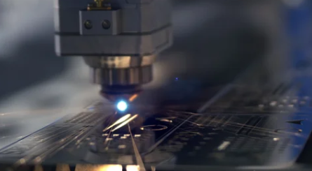
Every week, a drawing lands in our inbox for a laser or waterjet job, and it is not quite ready to cut. That is normal, and nobody here minds. Still, most buyers never see what happens next. Our DXF file requirements exist for one reason: a clean file gets quoted faster and cut sooner. Here is what actually happens on our end when a file arrives incomplete, plus the seven problems we run into most.
Your file goes to a programmer, not a salesperson. That programmer opens it in our CAM software and tries to build a toolpath. If the geometry is clean, that takes a few minutes. If it is not, the job stops right there.
Then the back-and-forth starts. We email you. You check with your designer. Your designer re-exports. We look again. Meanwhile, your part is not on the nest, and the nest is what reserves actual machine time. So a file that needs one round of cleanup can easily add two or three days to a quote. The cut itself was never the hard part. The clock simply kept resetting.
Typically, that delay traces back to two or three small DXF file requirements that got missed at export. Our DXF file requirements are not a gatekeeping exercise, though. They are the shortest path to getting your parts on a table.
Here they are, counted down from mildly annoying to completely job-stopping.
A DXF has no idea what is a part and what is documentation. To the machine, a dimension line is just a line. Therefore, we have to strip out title blocks, leader lines, hatching, and stray text before we can nest anything. Send the part geometry on its own layer instead, and put your notes in the body of the email.
DXF does not store units the way you might expect. The format has a header variable called $INSUNITS that is supposed to declare inches or millimeters. However, plenty of files leave it blank, and some software ignores it entirely. As a result, a four-inch bracket can import as a four-millimeter one. Always state the units in writing. It takes five seconds and removes all doubt.
This one is invisible on screen. Two identical lines sit exactly on top of each other, usually from a copy-paste or an exploded block. The machine cannot tell they are duplicates, so it cuts the same path twice. Consequently, you pay for extra cycle time and risk a rough, over-burned edge. Most CAD packages include an overkill or merge-duplicates command. Run it before you export.
Splines look smooth in CAD. In CAM, though, they break down into hundreds of tiny segments, which slows the cutting head and can leave visible faceting on a curve. Convert splines to arcs and polylines whenever your software allows it. Your curves will cut faster and look better.
Some drawings arrive scaled to fit a sheet. Others come from a PDF trace that is close but not exact. Either way, we cannot spot it by eye. So draw the part at full size and skip the paper-space layout entirely. Model space, 1:1, real dimensions.
Every cutting process removes material. Our fiber lasers run a .004″ beam kerf, and waterjet kerf is wider still. We account for it. Even so, we need to know whether the dimension in your file is the finished part size or the cut path. Additionally, tell us which feature is critical. If a bolt hole has to line up with an existing weldment, say so, and we will hold that dimension.
This is the big one. A profile that looks closed on screen may hide a .0003″ gap at one corner. CAM software cannot tell inside from outside on an open profile, so it will not generate a toolpath at all. That silence is usually why your quote goes quiet. Of all our DXF file requirements, this is the one worth checking twice. Before you export, join everything into closed polylines and run your software’s audit or gap-check tool.
Sixty seconds with this list will save you days on the back end.
Meeting these DXF file requirements will not turn you into a programmer. It will, however, get your quote back the same day far more often.
Here is the part we want you to hear. We would rather see a rough file today than a perfect file next week. Our programmers look at drawings all day, and they will tell you exactly what needs to change. Sometimes we simply fix it here in ten minutes and move on. Either way, we will walk you through the DXF file requirements as we go.
If you are still choosing between processes, our breakdown of laser cutting versus waterjet cutting is a good place to start. You can also browse our in-house processing services, from laser cutting to plasma and CNC machining.
Otherwise, just send the drawing. Email it over, request a quote online, or call us at (509) 482-4435. We are at 4510 North Freya in Spokane, and walk-ins are always welcome.
A walkthrough of how an order actually moves through our Spokane metals service center, from the front counter to the loading dock.
Every week, a drawing lands in our inbox for a laser or waterjet job, and it is not quite ready to cut. That is normal, and nobody here minds. Still,